Multimeter
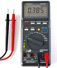
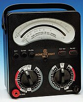
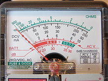
The D'Arsonval–Weston meter movement uses a moving coil which carries a pointer and rotates on pivots or a taut band ligament.Instead of balancing a bridge, values could be directly read off the instrument's scale, which made measurement quick and easy.The basic moving coil meter is suitable only for direct current measurements, usually in the range of 10 μA to 100 mA.[9] The invention of the first multimeter is attributed to British Post Office engineer, Donald Macadie, who became dissatisfied with the need to carry many separate instruments required for maintenance of telecommunication circuits.[10] Macadie invented an instrument which could measure amperes (amps), volts and ohms, so the multifunctional meter was then named Avometer.The technical specifications of these devices were often crude, for example the one illustrated has a resistance of just 25 Ω/V, a non-linear scale and no zero adjustment on both ranges.[15][16] It is claimed that the first handheld digital multimeter was developed by Frank Bishop of Intron Electronics in 1977,[17] which at the time presented a major breakthrough for servicing and fault finding in the field.A switch (usually rotary) allows greater resistance to be inserted in series with the meter movement to read higher voltages.To measure alternating current, which changes up and down repeatedly, a rectifier is inserted in the circuit so that each negative half cycle is inverted; the result is a varying and nonzero DC voltage whose maximum value will be half the AC peak to peak voltage, assuming a symmetrical waveform.[21] To measure resistance, switches arrange for a small battery within the instrument to pass a current through the device under test and the meter coil.Since the current available depends on the state of charge of the battery which changes over time, a multimeter usually has an adjustment for the ohm scale to zero it.Where AC measurements are required, the rectifier can be placed after the amplifier stage, improving precision at low range.Such amplified multimeters are called VTVMs (vacuum tube voltmeters),[23] TVMs (transistor volt meters), FET-VOMs, and similar names.For this reason, some digital multimeters additionally have a bar graph as a second display, typically with a more rapid sampling rate than used for the primary readout.These fast sampling rate bar graphs have a superior response than the physical pointer of analog meters, obsoleting the older technology.Meter movements as separate components may be protected in the same manner by connecting a shorting or jumper wire between the terminals when not in use.High-quality analog multimeters continue to be made by several manufacturers, including Chauvin Arnoux (France), Gossen Metrawatt (Germany), and Simpson and Triplett (USA).An autoranging digital multimeter can automatically adjust the scaling network so the measurement circuits use the full precision of the A/D converter.Measurement enhancements available include: Modern meters may be interfaced with a personal computer by IrDA links, RS-232 connections, USB, Bluetooth, or an instrument bus such as IEEE-488.A common error when operating a multimeter is to set the meter to measure resistance or current, and then connect it directly to a low-impedance voltage source.[33] Each Category rating also specifies maximum safe transient voltages for selected measuring ranges in the meter.[36] On meters that allow interfacing with computers, optical isolation may be used to protect attached equipment against high voltage in the measured circuit.[citation needed] Meters intended for testing in hazardous locations or for use on blasting circuits may require use of a manufacturer-specified battery to maintain their safety rating.The accuracy of a digital multimeter may be stated in a two-term form, such as "±1% of reading +2 counts", reflecting the different sources of error in the instrument.The accuracy of an analog instrument usually refers to full-scale deflection; a measurement of 30 V on the 100 V scale of a 3% meter is subject to an error of 3 V, 10% of the reading.An average responding multimeter will only meet its specified accuracy on AC volts and amps for purely sinusoidal waveforms.Multimeters designed for (mains) "electrical" use instead of general electronics engineering use will typically forego the microamps current ranges.RMS sensing is necessary for measurements on non-sinusoidal periodic waveforms, such as found in audio signals and variable-frequency drives.A quality general-purpose electronics digital multimeter is generally considered adequate for measurements at signal levels greater than 1 mV or 1 μA, or below about 100 MΩ; these values are far from the theoretical limits of sensitivity, and are of considerable interest in some circuit design situations.These include nanovoltmeters, electrometers (for very low currents, and voltages with very high source resistance, such as 1 TΩ) and picoammeters.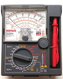


measuring instrumentvoltageresistancecurrentvoltmeterohmmeterammetercapacitancemicroammeterOxford English DictionarygalvanometerWheatstone bridgeD'Arsonval–WestonAvometertelecommunication circuitsamperessensitivitynon-linearvoltmetersinput impedancetransistorfield effect transistorsample-and-holdclamp metermicroampsdecibelsfrequencyduty cyclebuzzerthermocoupleinductancecomputeralternatingdirectburden voltagefaradsdissipation factorConductancesiemenspercentagehenriesTemperatureCelsiusFahrenheittest probeContinuity testerDiodesTransistorscurrent gainparameterssensorsLuminanceSound pressureRelative humidityHall effectvoltage dividershuntsrectifierroot mean squared'Arsonvalvacuum tubesfield effect transistorsradio frequency interferencedynamic brakingbattery chargingportable electronicsparallaxembedded computersignificant digitselectric polaritySample and holdvoltage dropsemi conductor junctionstransistor testercurve tracerbar graphoscilloscopedata acquisitionsamplessurface-mount technologyLCR meterpersonal computerRS-232BluetoothIEEE-488Crocodile clipssurface-mount devicesbanana jacksBNC connectorsbinding postsClamp metersconductorIEC61010 categoriesoptical isolationVaristorPolyswitchhazardous locationsblasting circuitsdigitsresolvedresolutionaccuracydecimal separatorparts per millionfrequenciescalibrationNational Institute of Standards and Technologystandards organizationmetrologycrest factormegohmsstandardizationprobesunbufferedimpedanceelectronics engineeringshunt resistancerectifier circuitsinusoidalwaveformwaveformsperiodicvariable-frequency driveselectrometersthermal noiseElectronic test equipment