Turbofan
[7] Whittle envisioned flight speeds of 500 mph in his March 1936 UK patent 471,368 "Improvements relating to the propulsion of aircraft", in which he describes the principles behind the turbofan,[8] although not called as such at that time.The working substance of the thermodynamic cycle is the only mass accelerated to produce thrust in a turbojet which is a serious limitation (high fuel consumption) for aircraft speeds below supersonic.A turbofan does this by transferring energy available inside the engine, from the gas generator, to a ducted fan which produces a second, additional mass of accelerated air.[23] Extracting shaft power and transferring it to a bypass stream introduces extra losses which are more than made up by the improved propulsive efficiency.[29] Modern commercial aircraft employ high-bypass-ratio (HBPR) engines with separate flow, non-mixing, short-duct exhaust systems.[38] Early turbojet engines were not very fuel-efficient because their overall pressure ratio and turbine inlet temperature were severely limited by the technology and materials available at the time.The original low-bypass turbofan engines were designed to improve propulsive efficiency by reducing the exhaust velocity to a value closer to that of the aircraft.The Rolls-Royce Conway, the world's first production turbofan, had a bypass ratio of 0.3, similar to the modern General Electric F404 fighter engine.Civilian turbofan engines of the 1960s, such as the Pratt & Whitney JT8D and the Rolls-Royce Spey, had bypass ratios closer to 1 and were similar to their military equivalents.A smaller core flow/higher bypass ratio cycle can be achieved by raising the inlet temperature of the high-pressure (HP) turbine rotor.The resulting turbofan, with reasonable efficiencies and duct loss for the added components, would probably operate at a higher nozzle pressure ratio than the turbojet, but with a lower exhaust temperature to retain net thrust.Some low-bypass ratio military turbofans (e.g. F404, JT8D) have variable inlet guide vanes to direct air onto the first fan rotor stage.The variable geometry nozzle must open to a larger throat area to accommodate the extra volume and increased flow rate when the afterburner is lit.Afterburning is often designed to give a significant thrust boost for take off, transonic acceleration and combat maneuvers, but is very fuel intensive.Low-bypass military turbofans include the Pratt & Whitney F119, the Eurojet EJ200, the General Electric F110, the Klimov RD-33, and the Saturn AL-31, all of which feature a mixed exhaust, afterburner and variable area propelling nozzle.Unlike some military engines, modern civil turbofans lack stationary inlet guide vanes in front of the fan rotor.More recent large high-bypass turbofans include the Pratt & Whitney PW4000, the three-shaft Rolls-Royce Trent, the General Electric GE90/GEnx and the GP7000, produced jointly by GE and P&W.[47] Although far from common, the single-shaft turbofan is probably the simplest configuration, comprising a fan and high-pressure compressor driven by a single turbine unit, all on the same spool.At the smaller thrust sizes, instead of all-axial blading, the HP compressor configuration may be axial-centrifugal (e.g., CFE CFE738), double-centrifugal or even diagonal/centrifugal (e.g. Pratt & Whitney Canada PW600).Turbofan engines can be made more fuel efficient by raising overall pressure ratio and turbine rotor inlet temperature in unison.Exotic alloys, sophisticated air cooling schemes and special mechanical design are needed to keep the physical stresses within the strength of the material.Advances in computational fluid dynamics (CFD) modelling have permitted complex, 3D curved shapes with very wide chord, keeping the fan capabilities while minimizing the blade count to lower costs.[52] Rolls-Royce pioneered the hollow, titanium wide-chord fan blade in the 1980s for aerodynamic efficiency and foreign object damage resistance in the RB211 then for the Trent.[53] Pratt & Whitney VP technology and environment Alan Epstein argued "Over the history of commercial aviation, we have gone from 20% to 40% [cruise efficiency], and there is a consensus among the engine community that we can probably get to 60%".[55] In summer 2017 at NASA Glenn Research Center in Cleveland, Ohio, Pratt has finished testing a very-low-pressure-ratio fan on a PW1000G, resembling an open rotor with fewer blades than the PW1000G's 20.[54] The weight and size of the nacelle would be reduced by a short duct inlet, imposing higher aerodynamic turning loads on the blades and leaving less space for soundproofing, but a lower-pressure-ratio fan is slower.It is demonstrating a counterrotating open rotor unducted fan (propfan) in Istres, France, under the European Clean Sky technology program.When noise levels are within existing standards and similar to the LEAP engine, 15% lower fuel burn will be available and for that Safran is testing its controls, vibration and operation, while airframe integration is still challenging.Nearly stoichiometric turbine entry temperature approaches the theoretical limit and its impact on emissions has to be balanced with environmental performance goals.The CFM LEAP introduction had been smoother but a ceramic composite HP Turbine coating was prematurely lost, necessitating a new design, causing 60 A320neo engine removals for modification and delaying deliveries by up to six weeks late.
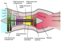
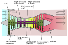
- Low-pressure spool
- High-pressure spool
- Stationary components
- Nacelle
- Fan
- Low-pressure compressor
- High-pressure compressor
- Combustion chamber
- High-pressure turbine
- Low-pressure turbine
- Core nozzle
- Fan nozzle


propfanturbopropCentrifugal fanAircraft propulsionShaft enginespropellersrotorsducted fanspropfansInternal thermal enginesPiston engineDiesel engineWankel engineTurbinesTurboshaftExternal thermal enginesSteam powerElectric motorsElectric aircraftClockworkHuman-poweredReaction enginesTurbojetRocket-poweredAir turborocketAir-augmented rocketMotorjetPulsejetValveless pulsejetGluhareff Pressure JetAerospike enginePulse detonation engineRotating detonation engineRamjetScramjetShcramjetairbreathing jet enginegas turbine enginemechanical energyducted fancombustion chamberthrustbypass ratiojet thrustfighterAfterburnersvacuum ejectorFrank Whittlespecific thrustspecific fuel consumptionlift fanPratt & Whitney J58Propellerpropelling nozzleturbopropsturbojetseffective exhaust velocityGEnx-2Bjet noiseacoustic linersnacelleaerospacejet enginenoise reductionBoeing 787Boeing 747-8Rolls-Royce Trent 1000General Electric GEnxRolls-Royce ConwayBoeing 707General Electric GEnx-2BBoeing 747–8overall pressure ratioDaimler-Benz DB 670Ministry of AviationMetrovick F.2Bristol OlympusPratt & Whitney JT3CthermodynamicGeneral Electric F404Pratt & Whitney JT8DRolls-Royce SpeyTupolev Tu-124Soloviev D-20AeroflotEastern BlocCJ805-23General Electric CF700General Electric J85/CJ610Rockwell SabrelinerDassault Falcon 20Federal Aviation AdministrationProject ApolloLunar Landing Research Vehiclecompressor mapjetlinersSoloviev D-30Ilyushin Il-76Il-62MMikoyan MiG-31Xian H-6Saturn AL-31Chengdu J-10Shenyang J-11Sukhoi Su-30Williams F107RaytheonBGM-109 TomahawkNPO Saturn AL-55HAL HJT-36 SitaraPratt & Whitney TF-30Grumman F-14 TomcatEurojet EJ200Eurofighter TyphoonIshikawajima-Harima F3Kawasaki T-4GTRE GTX-35VS KaveriAfterburnerPratt & Whitney F119jet fighterstoichiometricPratt & Whitney TF30F-111 AardvarkF-14 TomcatGeneral Electric F110Klimov RD-33