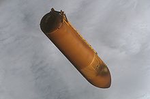
Space Shuttle external tank
[10] The SLWT had basically the same design as the LWT except that it used an aluminium-lithium alloy (Al 2195) for a large part of the tank structure.Although all ETs produced after the introduction of the SLWT were of this configuration, one LWT remained in inventory to be used if requested until the end of the shuttle era.The tank was manufactured at the Michoud Assembly Facility, New Orleans, and was transported to Kennedy Space Center by barge.The LOX tank is located at the top[a] of the ET and has an ogive shape to reduce aerodynamic drag and aerothermodynamic heating.The nose cone consists of a removable conical assembly that serves as an aerodynamic fairing for the propulsion and electrical system components.The LH2 tank also has a vortex baffle to reduce swirl resulting from slosh and to prevent entrapment of gases in the delivered LH2.This outlet transmits the liquid hydrogen from the tank through a 17 inches (430 mm) line to the left aft umbilical.The middle cylinder of the oxygen tank, and the propellant lines, could withstand the expected depths of frost accumulation condensed from humidity, but the orbiter could not take the damage from ice breaking free.During the lift-off of STS-107 on January 16, 2003, a piece of foam insulation detached from one of the tank's bipod ramps and struck the leading edge of Space Shuttle Columbia's wing at a few hundred miles per hour.The report determined that the external fuel tank, ET-93, "had been constructed with BX-250", a closeout foam whose blowing agent was CFC-11 and not the newer HCFC 141b.[17] In 2005, the problem of foam shed had not been fully cured; on STS-114, additional cameras mounted on the tank recorded a piece of foam separated from one of its Protuberance Air Load (PAL) ramps, which are designed to prevent unsteady air flow underneath the tank's cable trays and pressurization lines during ascent.However, on STS-118 a piece of foam (and/or ice) about 3.9 in (100 mm) in diameter separated from a feedline attachment bracket on the tank, ricocheted off one of the aft struts and struck the underside of the wing, damaging two tiles.This dual-function valve can be opened by ground support equipment for the vent function during prelaunch and can open during flight when the ullage (empty space) pressure of the liquid hydrogen tank reaches 38 psi (260 kPa) or the ullage pressure of the liquid oxygen tank reaches 25 psi (170 kPa).On early flights, the liquid oxygen tank contained a separate, pyrotechnically operated, propulsive tumble vent valve at its forward end.When the orbiter GPCs command external tank separation, the bolts are severed by pyrotechnic devices.As the ET is filled, excess gaseous hydrogen is vented through umbilical connections over a large diameter pipe on an arm extended from the fixed service structure.The connection for this pipe between the ET and service structure is made at the ground umbilical carrier plate (GUCP).Countdowns of STS-80, STS-119, STS-127 and STS-133 have been halted and resulted in several week delays in the later cases due to hydrogen leaks at this connection.This requires complete draining of the tanks and removal of all hydrogen via helium gas purge, a 20-hour process, before technicians can inspect and repair problems.[18] A cap mounted to the swing-arm on the fixed service structure covers the oxygen tank vent on top of the ET during the countdown and is retracted about two minutes before lift-off.Unexplained, erroneous readings from fuel depletion sensors have delayed several shuttle launch attempts, most notably STS-122.Originally configured like that of the Ares V and the Shuttle ET, NASA, upon completing its design review in 2006, decided, in order to save weight and costs, to reconfigure the internal structure of the second stage by using a combined LH2/LOX tank with the propellants separated by a common bulkhead, a configuration successfully used on the S-II and S-IVB stages of the Saturn V rocket.Because of the trade-off, NASA would save an estimated USD $35 million by using simplified, higher thrust RS-68 engines (reconfigured to fire and perform like the SSME), while at the same time, eliminate the costly tests needed for an air-startable RS-25 for the Ares I.It was planned to save $16 billion, eliminate NASA job losses, and reduce the post-shuttle, crewed spaceflight gap from five plus years to two or less.The core stage of the rocket is 8.4 meters (28 ft) in diameter and mount a Main Propulsion System (MPS) incorporating four RS-25 engines.[30][31] On January 15, 2024 it was announced in a press release that ET-94, 2 solid rocket boosters, and the Space Shuttle Endeavour had been linked together and expected them to be moved by the end of the month to their new exhibit location.


Drop tankTom ScottExternal Tank LimitedCategory of simplicial setsVehicle Assembly BuildingSTS-117Michoud Assembly FacilityMartin MariettaLockheed MartinSpace ShuttleorbiterSTS-115launch vehicleliquid hydrogenliquid oxygenoxidizerSolid Rocket BoostersIndian OceanPacific Oceanshipping laneshydrogenSpace Shuttle Solid Rocket Boostersumbilicalsfluidselectricalultraviolet light2219 aluminum alloygaseouspropellantSTS-114ill-fatedSTS-107milledsolid rocket boostertitaniumSTS-91STS-99aluminium-lithium alloyAl 2195International Space StationSTS-121cu ftUS galNew OrleansKennedy Space CenterAl 2090nose conecryogenicullageinsulationablatorphenolicaeroheatingColumbiaChallengerSTS-27AtlantisSTS-32STS-50STS-52STS-62chlorofluorocarbon-11Environmental Protection AgencyClean Air ActhydrochlorofluorocarbonHCFC-141bSTS-79STS-86destruction of ColumbiaSTS-116STS-118Discoverybeanie caprelief valvepyrotechnicallySTS-127STS-80STS-119STS-133cavitateSTS-122pressure transducersrange safety systembatteryordnanceSTS-88Constellation programOrion spacecrafthuman-ratedAres IAres VDelta IV rocketSaturn VAres IVMichael D. GriffinDIRECTSpace Launch Systemsuper heavy-liftexpendable launch vehicleArtemis 1U.S. Space & Rocket CenterMPTA-ETSpace Shuttle PathfinderHuntsville, AlabamaLos AngelesSpace Shuttle EndeavourCalifornia Science CenterList of reentering space debrisList of heaviest spacecraftWayback MachineBibcodeYouTubeSpace Shuttle programList of missionsList of crewsMain engineOrbital Maneuvering SystemReaction control systemThermal protection systemBooster separation motorOrbitersEnterpriseEndeavourSpacelabCanadarmExtended Duration Orbiter