Two-port network
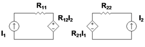
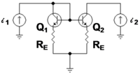
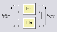
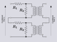
A two-port network is regarded as a "black box" with its properties specified by a matrix of numbers.For example, transistors are often regarded as two-ports, characterized by their h-parameters (see below) which are listed by the manufacturer.Any linear circuit with four terminals can be regarded as a two-port network provided that it does not contain an independent source and satisfies the port conditions.The analysis of passive two-port networks is an outgrowth of reciprocity theorems first derived by Lorentz.[3] In two-port mathematical models, the network is described by a 2 by 2 square matrix of complex numbers.The common models that are used are referred to as z-parameters, y-parameters, h-parameters, g-parameters, and ABCD-parameters, each described individually below.They are usually expressed in matrix notation, and they establish relations between the variables which are shown in figure 1.There are certain properties of two-ports that frequently occur in practical networks and can be used to greatly simplify the analysis.[7] Figure 3 shows a bipolar current mirror with emitter resistors to increase its output resistance.For example, when used as an active load in a differential amplifier, I1 ≈ −I2, making the output impedance of the mirror approximately compared to only rO without feedback (that is with RE = 0 Ω).At the same time, the impedance on the reference side of the mirror is approximately only a moderate value, but still larger than rE with no feedback.There are a number of definitions given for ABCD parameters, the most common is,[11][12] Note: Some authors chose to reverse the indicated direction of I2 and suppress the negative sign on I2.[6] This representation is preferred because when the parameters are used to represent a cascade of two-ports, the matrices are written in the same order that a network diagram would be drawn, that is, left to right.S-parameters are used primarily at UHF and microwave frequencies where it becomes difficult to measure voltages and currents directly.Some connections (when dissimilar potentials are joined) result in the port condition being invalidated and the combination rule will no longer apply.This difficulty can be overcome by placing 1:1 ideal transformers on the outputs of the problem two-ports.This does not change the parameters of the two-ports, but does ensure that they will continue to meet the port condition when interconnected.The total z-parameters predicted by matrix addition are; However, direct analysis of the combined circuit shows that, The discrepancy is explained by observing that R1 of the lower two-port has been by-passed by the short-circuit between two terminals of the output ports.This results in no current flowing through one terminal in each of the input ports of the two individual networks.This problem can be resolved by inserting an ideal transformer in the output port of at least one of the two-port networks.While this is a common text-book approach to presenting the theory of two-ports, the practicality of using transformers is a matter to be decided for each individual design.The following representations are also applicable to networks with an arbitrary number of ports: For example, three-port impedance parameters result in the following relationship: However the following representations are necessarily limited to two-port devices: A two-port network has four variables with two of them being independent.


Quadrupoleelectronicselectrical networkterminalscurrentscircuit analysisblack boxmatrixlinear circuitfiltersmatching networkstransmission linestransformerssmall-signal modelshybrid-pi modelcomplex numbersindependent variablescurrentvoltageenergyscattering parametersReciprocal networkscirculatorsisolatorsantimetrical networksImpedance parameterscurrent mirrorMiller effectAdmittance parameterssiemensdimensionlesscharacteristic impedancepropagation constantreflected wavesmicrowavedirectional couplersScattering transfer parametersBrune testdeterminantmatrix inverseAdmittance (y) parametersImpedance (z) parametersScattering (S) parametersone-portTransfer-matrix method (optics)Ray transfer matrixparallelDragica Vasileska