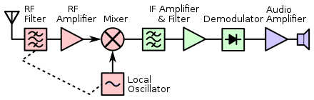
Superheterodyne receiver
Simple radio detectors filtered out the high-frequency carrier, leaving the modulation, which was passed on to the user's headphones as an audible signal of dots and dashes.Due to the filtering effects of the receiver, these signals generally produced a click or thump, which were audible but made determining dots from dashes difficult.In 1905, Canadian inventor Reginald Fessenden came up with the idea of using two Alexanderson alternators operating at closely spaced frequencies to broadcast two signals, instead of one.By selecting two carriers close enough that the beat frequency was audible, the resulting Morse code could once again be easily heard even in simple receivers.In contrast to voice broadcasts, the output of the amplifier didn't have to closely match the modulation of the original signal.In 1913, Edwin Howard Armstrong described a receiver system that used this effect to produce audible Morse code output using a single triode.When the original signal cut off at the end of the dot or dash, the oscillation decayed and the sound disappeared after a short delay.Many radio systems of the 1920s were based on the regenerative principle, and it continued to be used in specialized roles into the 1940s, for instance in the IFF Mark II.There was one role where the regenerative system was not suitable, even for Morse code sources, and that was the task of radio direction finding, RDF.He had concluded that moving to higher "short wave" frequencies would make RDF more useful and was looking for practical means to build a linear amplifier for these signals.Armstrong realized that this effect was a potential solution to the "short wave" amplification problem, as the "difference" output still retained its original modulation, but on a lower carrier frequency.[citation needed] When the signal from the LO mixes with the station's, one of the outputs will be the heterodyne difference frequency, in this case, 60 kHz.In December 1919, Major E. H. Armstrong gave publicity to an indirect method of obtaining short-wave amplification, called the super-heterodyne.This means the amplifier section can be tuned to operate at a single frequency, the design IF, which is much easier to do efficiently.It was less popular when commercial radio broadcasting began in the 1920s, mostly due to the need for an extra tube (for the oscillator), the generally higher cost of the receiver, and the level of skill required to operate it.Higher IF frequencies (455 kHz was a common standard) came into use in later years, after the invention of the tetrode and pentode as amplifying tubes, largely solving the problem of image rejection.By the mid-1930s, superheterodynes using much higher intermediate frequencies (typically around 440–470 kHz) used tuned transformers more similar to other RF applications.French engineer Lucien Lévy filed a patent application for the superheterodyne principle in August 1917 with brevet n° 493660.If the local oscillator frequency is less than the desired reception frequency, it is called low-side injection (fIF = fRF − fLO); if the local oscillator is higher, then it is called high-side injection (fIF = fLO − fRF).Most other signals produced by the mixer (such as due to stations at nearby frequencies) can be filtered out in the IF tuned amplifier; that gives the superheterodyne receiver its superior performance.[18] In the case of television receivers, no other technique was able to produce the precise bandpass characteristic needed for vestigial sideband reception, such as that used in the NTSC system first approved by the US in 1941.Fabricated by precision laser milling techniques, SAW filters are cheaper to produce, can be made to extremely close tolerances, and are very stable in operation.AM demodulation requires envelope detection, which can be achieved by means of rectification and a low-pass filter (which can be as simple as an RC circuit) to remove remnants of the intermediate frequency.Continuous wave and single sideband signals require a product detector using a so-called beat frequency oscillator, and there are other techniques used for different types of modulation.At shortwave frequencies and above, the difficulty in obtaining sufficient selectivity in the tuning with the high IFs needed for low image response impacts performance.Radio transmitters may also use a mixer stage to produce an output frequency, working more or less as the reverse of a superheterodyne receiver.The development of modern semiconductor electronics negated the advantages of designs (such as the regenerative receiver) that used fewer vacuum tubes.Regenerative and super-regenerative receivers offered a high sensitivity, but often suffer from stability problems making them difficult to operate.Reception at the image frequency can be combated through tuning (filtering) at the antenna and RF stage of the superheterodyne receiver.As a consequence, most Autodyne receivers required greater front-end selectivity, often involving double-tuned coils, to avoid image interference.


Toshibatransistor radioradio receiverfrequency mixingintermediate frequencycarrier frequencyLucien LévyMorse codealternatorspark gapalternating currentamplitude modulatedradio detectorsheadphonesErnst AlexandersonAlexanderson alternatorReginald Fessendenheterodynetriodecapacitive couplingEdwin Howard Armstrongfeedbackregenerative receiverIFF Mark IIradio direction findinglinear amplificationBritish Admiraltylocal oscillatorEdwin Armstrongradio broadcastingtuned radio frequency receiversWestinghouseRadio Corporation of America (RCA)transformersneutrodynetetrodepentodeselectivityceramic resonatorssurface acoustic waveAll American Fivetetrode with two control gridsautodynepentagrid converterWalter H. Schottkytransfer functionsimage frequencyantennafrequency mixerheterodyningband-pass filterdemodulatormodulationmicrovoltstuned circuitsvariable capacitorvaricap diodebandpass filterfilteredtuned amplifiervaractorstube (valve)medium-wavetooling costsQ multipliercrystal filterceramic crystal filterbandpassvestigial sidebandfiltersbasebandenvelope detectionrectificationlow-pass filterRC circuitphase-locked loopContinuous wavesingle sidebandproduct detectorbeat frequency oscillatorimage responseshortwavesoftware-defined radiomicroprocessorRadio transmitterssemiconductortuned radio frequency receiverQ factorRegenerativeRF front endimage rejection ratiodecibelsElectromagnetic compatibilityOperation RAFTERradar detector detectorsamplitude modulationphase modulationnon-linearAutomatic gain controlDirect conversion receiverH2X radarOptical heterodyne detectionReflex receiverSuperheterodyne transmitterAmerican Radio Relay LeagueAuthorHouseInstitution of Electrical EngineersSarkar, Tapan K.Oliner, Arthur A.Salazar-Palma, MagdalenaJohn Wiley and SonsCambridge University PressMcGraw HillLangford-Smith, FritzSpycatcher: The Candid Autobiography of a Senior Intelligence OfficerPenguin VikingCRC PressFessenden, Reginald A.Pitman & SonsHogan, John L. Jr.Schottky, Walter H.Wayback MachineTelecommunicationsHistoryBroadcastingCable protection system