Curtain array
[1] These are suspended by support wires strung between pairs of tall steel towers, reaching heights of up to 90 m (300 feet) high.Curtain arrays are extensively used by international short-wave radio stations for broadcasting to large areas at transcontinental distances.This allows most of the radiation to be concentrated in a narrow main lobe aimed a few degrees above the horizon, which is ideal for skywave transmission.In order to allow the beam to be steered, sometimes the entire array is suspended by cantilever arms from a single large tower which can be rotated.Adding a constant phase shift between adjacent horizontal dipoles allows the direction of the beam to be slewed in azimuth up to ±30° without losing its radiation pattern.Geopolitical necessity leads some international broadcasters to occasionally use three separate antenna arrays: highband and midband, as well as lowband HRS curtains.An example of this can be seen at NRK Kvitsøy, where a circular railway carries a pair of wheeled platforms, each of which supports a tower at opposite ends of a diameter-arm.The number of dipole rows and the height of the lowest element above ground determine the elevation angle and consequently the distance to the service area.Note that it is possible for details of the antenna site to wreak havoc with the designers plans such that takeoff angle and matching may be adversely affected.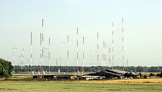


Radio Free Europedirectionalantennasshort-wavereflective array antennadipole antennasskywaveionosphereradio stationspropagandaRadio LibertyEastern Europeshortwavedipole antennaGuglielmo MarconiCharles Samuel FranklinEdmond BruceSterba curtainBell TelephoneHörbyRadio SwedenChain HomeCold WarVoice of Americadriven elementswavelengthvertical polarizationhorizontally polarizedmain lobeimpedance matchingfolded dipoleALLISS-Antennaphased arraysphase shifteramplifiersphase shiftazimuthRadio France Internationale (RFI)Issoudun Relay stationradiation patternEsquimaltsidelobesOver The Horizon Radarshortwave relay stationmap projectionALLISSadjustment of the electrical wave phasesAustralasiaIndonesiaLatin AmericaEmpresa Brasil de ComunicaçãoGermanyT-SystemsNew ZealandRangitaikiAscension IslandRampishamSkeltonWooffertonWayback MachineAustraliaDarwin, NTRadio AustraliaWertachtalCanadaRadio Canada InternationalSackville, NBDelano, CaliforniaBeaufort County, North CarolinaAntennaIsotropicIsotropic radiatorOmnidirectionalBatwing antennaBiconical antennaCage aerialCoaxial antennaCrossed field antennaDielectric resonator antennaDiscone antennaFolded unipole antennaG5RV antennaHalo antennaHelical antennaInverted-F antennaInverted vee antennaJ-pole antennaMast radiatorMonopole antennaRandom wire antennaRubber ducky antennaSloper antennaTurnstile antennaT2FD antennaT-antennaUmbrella antennaWhip antennaAdcock antennaAWX antennaBeverage antennaCantennaCassegrain antennaChoke ring antennaCollinear antenna arrayConformal antennaCorner reflector antennaFolded inverted conformal antennaFractal antennaGizmotchyHorn antennaLog-periodic antennaLoop antennaMicrostrip antennaMoxon antennaOffset dish antennaPatch antennaPhased arrayPlanar arrayParabolic antennaPlasma antennaQuad antennaRegenerative loop antennaRhombic antennaSector antennaShort backfire antennaSlot antenna