Bending moment
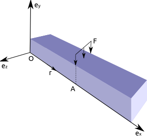
[1][2] The most common or simplest structural element subjected to bending moments is the beam.The diagram shows a beam which is simply supported (free to rotate and therefore lacking bending moments) at both ends; the ends can only react to the shear loads.[3] For equilibrium, the moment created by external forces/moments must be balanced by the couple induced by the internal loads.Moments and torques are measured as a force multiplied by a distance so they have as unit newton-metres (N·m), or pound-foot (lb·ft).Tensile and compressive stresses increase proportionally with bending moment, but are also dependent on the second moment of area of the cross-section of a beam (that is, the shape of the cross-section, such as a circle, square or I-beam being common structural shapes).Failure in bending will occur when the bending moment is sufficient to induce tensile/compressive stresses greater than the yield stress of the material throughout the entire cross-section.In structural analysis, this bending failure is called a plastic hinge, since the full load carrying ability of the structural element is not reached until the full cross-section is past the yield stress.When analysing an entire element, it is sensible to calculate moments at both ends of the element, at the beginning, centre and end of any uniformly distributed loads, and directly underneath any point loads.Of course any "pin-joints" within a structure allow free rotation, and so zero moment occurs at these points as there is no way of transmitting turning forces from one side to the other.It is more common to use the convention that a clockwise bending moment to the left of the point under consideration is taken as positive.This then corresponds to the second derivative of a function which, when positive, indicates a curvature that is 'lower at the centre' i.e. sagging.When defining moments and curvatures in this way calculus can be more readily used to find slopes and deflections.Critical values within the beam are most commonly annotated using a bending moment diagram, where negative moments are plotted to scale above a horizontal line and positive below.Engineering descriptions of the computation of bending moments can be confusing because of unexplained sign conventions and implicit assumptions.The descriptions below use vector mechanics to compute moments of force and bending moments in an attempt to explain, from first principles, why particular sign conventions are chosen.For many problems, it is more convenient to compute the moment of force about an axis that passes through the reference point O.The adjacent figure shows a beam that is acted upon by a force, we have Then, For this new choice of axes, a positive moment tends to rotate body clockwise around an axis.These internal forces will cause local deformations in the body.[1] Though bending moments have been used to determine the stress states in arbitrary shaped structures, the physical interpretation of the computed stresses is problematic.For example, in a beam in the figure, the bending moment vector due to stresses in the cross-section A perpendicular to the x-axis is given by Expanding this expression we have, We define the bending moment components as The internal moments are computed about an origin that is at the neutral axis of the beam or plate and the integration is through the thickness (Balancing the moments about any arbitrary point X would give us a second equation we can use to solve foris the length of the beam, we have Evaluating the cross-products: If we solve for the reactions we have Now to obtain the internal bending moment at X we sum all the moments about the point X due to all the external forces to the right of X (on the positiveside), and there is only one contribution in this case, We can check this answer by looking at the free body diagram and the part of the beam to the left of point X, and the total moment due to these external forces is If we compute the cross products, we have Thanks to the equilibrium, the internal bending moment due to external forces to the left of X must be exactly balanced by the internal turning force obtained by considering the part of the beam to the right of X which is clearly the case.In the above discussion, it is implicitly assumed that the bending moment is positive when the top of the beam is compressed.That can be seen if we consider a linear distribution of stress in the beam and find the resulting bending moment.Therefore, the bending moment is positive when the top of the beam is in compression.is defined as In that case, positive bending moments imply that the top of the beam is in tension.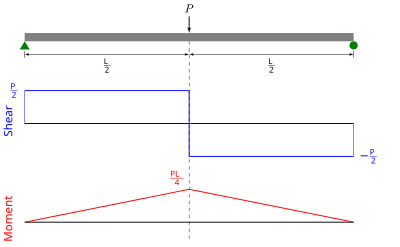

Shear and moment diagramsolid mechanicsreactionstructural elementmomentcantilevercross-sectionresultant forcecoupleshear forcenormal forceequilibriumhoggingsaggingcontraflexuretorquesnewton-metrespound-footengineeringmechanical engineeringphysicsTensilecompressivesecond moment of areavectorforcesbending moment diagramdot productstress resultantsarea moment of inertiaBucklingDeflectionTwisting momentShear and moment diagramsFirst moment of areaInfluence lineList of area moments of inertiaStructural engineeringHistoryDuhamel's integralModal analysisBetti's theoremCastigliano's methodConjugate beam methodFlexibility methodMacaulay's methodMoment-area theoremStiffness methodTheorem of three momentsStructural elementsI-beamLintelPost and lintelCompression memberThin-shell structureStructural supportBracketEuler–Bernoulli beam theoryMohr–Coulomb theoryPlate theoryTimoshenko–Ehrenfest beam theory