Conoscopic interference pattern

The thin section containing the mineral to be investigated is placed on the microscope stage, above one linear polariser, but with a second (the "analyser") between the objective lens and the eyepiece.The microscope's condenser is brought up close underneath the specimen to produce a wide divergence of polarised rays through a small point, and light intensity increased as much as possible (e.g., turning up the bulb and opening the diaphragm).This both maximises the solid angle subtended by the lens, and hence the angular variation of the light intercepted, and also increases the likelihood that only a single crystal will be viewed at any given time.Such crystal orientations are findable in thin section by looking for slices through minerals which are not isotropic but that nevertheless appear uniformly black or very dark grey under normal cross-polarised light at all stage angles (i.e., are "extinct").An interference figure produced looking straight down or close to the optic axis of a uniaxial mineral will show a characteristic "Maltese" cross shape to its isogyres.On either side of the "saddle" formed by the isogyres, birefringent rings of colour run concentrically around two eye like shapes called melatopes.
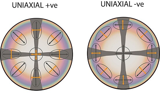
Sketches of uniaxial interference figures, viewed along the optic axis of each mineral. The colours approximate birefringence colours which might be seen if this were a mineral with second order maximum birefringence. The dark "maltese cross" pattern is characteristic of uniaxial minerals. Also shown are schematics of the shape of a cross section through the mineral's optical indicatrix (recording its refractive index in 3D) that would be seen at each position. The elongated direction could be distinguished by adding a sensitive tint plate to the microscope, letting the user discriminate between "uniaxial positive" (left) and "uniaxial negative" (right) minerals.
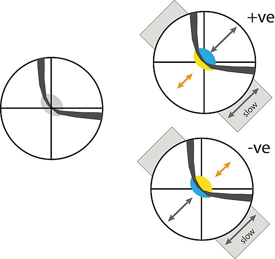
Possible interference figures for a biaxial mineral with a large 2V, viewed along one of its two optic axes. The curved shape of the isogyre is characteristic of biaxial minerals – though the degree of curvature will change as the microscope stage is rotated, and at some orientations the pattern will resemble the "maltese cross" pattern of a uniaxial mineral. The left hand image illustrates the figure alone; the grey patch at the centre indicates the low first order (grey) birefringence colours seen here (the order of the colours seen would in reality increase away from the center, but these colours are not shown). The two right hand figures show the effect of adding a sensitive tint plate to the setup, replacing the grey at the centre with second order blue and first yellow birefringence colours. The polarity of the yellow and blue reveals whether the mineral being viewed is optically "biaxial positive" (top) or "biaxial negative" (bottom), which can be a key property in identifying the mineral (or investigating its composition).
birefringentgeologicalpetrographic microscopemineralmineral optical and chemical propertiesoptical interferencerefractive indexoptical extinctionsensitive tint plateoptical mineralogypolarised lightthin sectionlinear polariserobjective lenseyepiececondenserBertrand lensoptic axisextinctbirefringenceindicatrix"Maltese" crossextinction positionscrystal structureolivinesoptical indicatrixMichel-Levy ChartWave interference